Archive for July, 2010

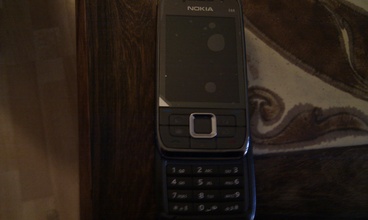
Revitalizing an aging Nokia E66 mobile phone

Tuesday, July 27th, 2010

I had decided to give my wife my E66, but my E66 was pretty much worn out. The case had started to fall apart and there was dust beneath the glass protecting the TFT screen.

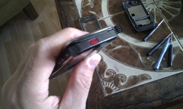
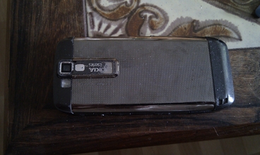
What was wrong with the E66? (broken fascia)

What was wrong with the E66? (wear and tear)

It is possible to buy spareparts for mobile phones though. Buying them from a local dealer in your country will surely set you back many many dollars. Luckily Ebay came to the rescue. I bought a new fascia housing for my Nokia E66. Only  set me back around $10.

The seller states:

NOT supplied fitting manual
Replacing your phone with this new fascia, the preference to phone shop engineering maintainers or alternatively change it by yourself with any of corresponding tools.

So this blogpost constitutes a walkthrough on how to replacing the fascia, in case somebody else decides to revitalizing his or hers aging Nokia E66.

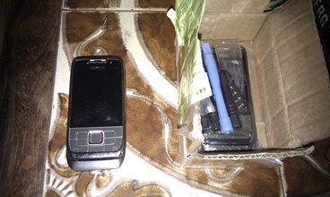
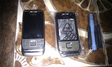
What was in the package from the seller?

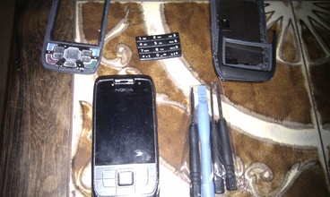
Old phone and new package

Unpacking the new stuff (fascia and 3 screwdrivers)

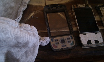
Unpacking (taking the new fascia apart)

I then started to take the old phone apart. Gently, noting where everything went. This is not the time where you want to have leftovers afterwards!

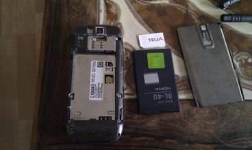
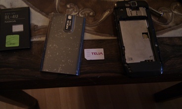
Taking the E66 apart (remove battery and SIM)

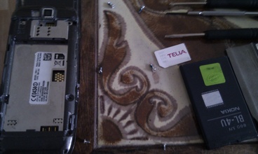
Next up, remove the screws. Notice carefully what screws belongs to what hole. There are 3 different screws on the back.

Taking the E66 apart (reming the 6 screws from the back)

Next seperate the front and the back from the actual phone mainboard. Do this very very carefully. Do not get angry! And do not use excessive force. Everything in the phone are hold together using plastic tabs at this point.

Detaching the phone mainboard from the back and front

The two connectors from the front and back PCB to the main PCB needs to be detached gently. They will come off without force if you do it right.

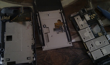
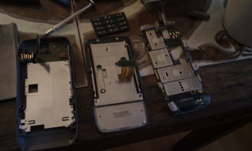
The front and back cover seperated from the mainboard

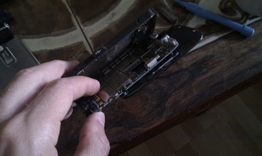
Working on the back, you need to detach the PCB where all the buttons are located. Gently use a thin screwdriver for this. You also need to detach the power connector. That is most easily done by putting a screwdriver into the powerconnector, tipping the screwdriver downwards. That will make the connector pop out of its plastic tabs.

The button PCB of the back being detached

The button PCB hanging in midair

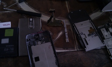
The button PCB and power connector removed

Assembling the back is just the reverse process. Keywords are: patience, low force, patience

Attaching power and button PCB onto new back fascia

Back part done

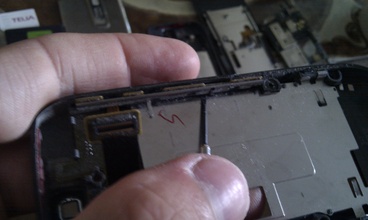
Working on the front part. Unscrew the two screws holding the PCB onto the slider. Do not fall for the urge to do anything about the spring system!! If you do, you will not get a working phone afterwards!

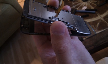
After unscrewing the two screws, you can pull the PCB out of the fascia. I then cleaned the TFT and put the PCB into the new fascia.

Seperating the front and cleaning it

Putting the front PCB into the new fascia

Front and back fascia was now done.

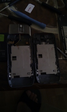
Front and back are exchanged

Assembly of the parts again. Just reverse the steps you did when taking the phone apart.

Only battery and SIM missing

And then

All done

And it is still alive, who should have thought that ;-)

It is alive

Got myself a HTC Desire mobile

Thursday, July 22nd, 2010

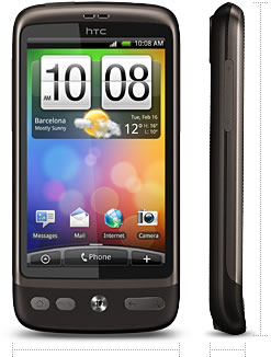
My wife complained about her Nokia 6700 classic was a real pain to use for SMS’s. She tried my Nokia E66 and found it to be much better. As the true gentleman I am, I imediatly gave her my E66 — it was almost two years since I got it anyway. Having given her my phone, I had none. On the other hand,  that provided me with an excuse for buying a new one.  More specifiically an  HTC Desire.

HTC Desire

The phone arrived today and after having used it for some hours I can say that it is a fine piece of equipment. Useful as a phone, useful as a toy, useful as a tool, useful as a camera, voice recorder, media player. You name it. I am quite sure that we will get along just fine :-)

How to use a broken IBM Thinkpad T43 for something useful using puppy linux.

Wednesday, July 21st, 2010

I recently got my hands on a IBM Thinkpad T43. Unfortunately it was broken. More specifically the connector between the mainboard and the harddrive had problems.

IBM T43 connector (broken)

I googled a bit and discovered, that this was a known problem. The laptop worked fine, if I put pressure on the right spot on the case of the Thinkpad. Otherwise it would not detect and/or spin up the harddrive. I tried to fix it by re-soldering the connector and using some two-component glue to fixate the connector. I did not succeed :-/

So then what? Throw out the laptop? Or? … I decided to make a project out of it.

A laptop without storage is useless. Due to the broken connector, I could not use a harddrive. I did not want to use a cdrom as it is a slow medium. That left me with a USB flash drive as the only option. It would be a clumsy solution just to plug a USB flash drive into the laptop and be done with it, so I chose to solder a USB flash directly onto the mainboard.

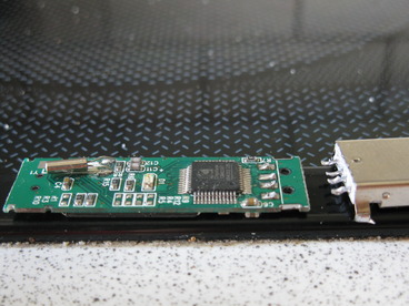
First I stripped a standard 1GB USB Flash from its case and detached the PCB from the USB connector using a soldering iron

Stripped USB flash

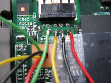
After that I soldered 5 wires onto the PCB of the laptop and used one of the holes in the PCB used for assembly as a pass through hole. I initially used 4 wires as the USB connector only had 4 pins, but that was not enough. More on that later.

Wires soldered onto mainboard

Having soldered the wires onto to the mainboard, I now needed to solder the other ends onto to the PCB of the USB flash. That went fairly smoothly

Wires soldered onto flash

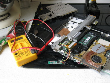
Before powering on anything, I used a multimeter to check for bad solderjoins and shorts. I found neither.

Checking for shorts using digital multimeter

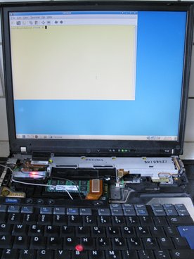
Luckily I had a Linux based rescue distribution installed on the USB flash drive, so I just booted that to see if the operation on the T43 was a success. As can be seen below it worked just fine. Well, sort of fine, but more on that in a moment.

Testbooting the flashdrive

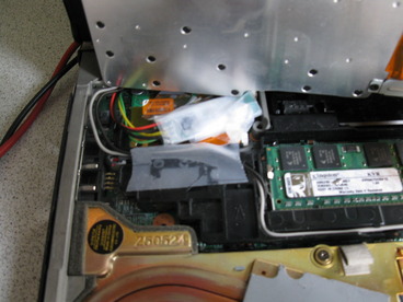
Almost done now. I just needed to assemble the laptop again, leaving the USB Flash inside.

Ready to wrap up

Closing the lid on the laptop, securing all the screws I had myself a working IBM Thinkpad T43. Or so I thought. When I tested the laptop thoroughly I discovered that the kernel ring buffer was filled with

hub 2-0:1.0: over-current change on port 1
hub 2-0:1.0: over-current change on port 2

That cryptic message just states that the USB device is drawing more power than it is allowed to by the USB specification. Or more precisely that the port on the USB hub inside the laptop is delivering more power than it was supposed to. It first that puzzled me. Then I read about the USB connector and realized my fail. The 4 wires of the USB connector consists of  VCC, GND, Data+ and Data –. Given both VCC and GND was part of the 4 pins I only soldered 4 pins. After seeing the problems above, I investigated the matter and found a reference to OverCurrent (OC) protection on the header itself. I thus soldered the 5th pin and the problem went away.

I now had a working IBM Thinkpad T43 with 1GB of flash storage. What should I use it for? I decided to use it for puppy linux. Primarily for two reasons.

  1. It appeared to be tailor made for small harddrives
  2. I had never tried it before

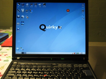
I downloaded the 106MB large iso file and burned it onto a CDrom. Now I faced the problem of installing puppy linux onto my flash without using a cdrom drive (as I found the laptop without one). Puppy linux made it quite easy. Using another computer I booted the cdrom. Installed puppy onto a spare flash drive. Booted that flash drive in my IBM Thinkpad T43 and pressed “install” once more, installing it onto the “internal” flash drive.

Booted into puppy linux

All done. Actually it takes quite some time to boot the machine, but that is primarily due to the bios insisting on searching for a harddrive. Unfortunately the IBM BIOS lacks the option to stop it from doing that. After the system is loaded however, it is lightning fast. Way faster than my IBM Thinkpad T400. This is due to the fact that puppy linux loads everything into a ramdisk, so starting program does not require any moving parts to be ready. Programs starts instantaneously. The whole experience just proves (once more), that the computers of today is severely I/O limited, but hopefully SSD will change that real soon now(tm)